Unijunction Transistor Tutorial

The unijunction transistor (UJT) is made of a bar of N type material with a P type junction (the emitter) near the centre. Base 1 is connected to zero volts and base 2 to the positive supply. The resistance between the two bases (the INTERBASE RESISTANCE) is typically 10k.
With the emitter unconnected, the bar acts as a potential divider, and about 0.5 volts appears at the emitter. If a voltage is connected to the emitter, as long as it is less than 0.5 volts, nothing happens, as the P-N junction is reversed biased. (see the right hand diagram).
When the emitter voltage exceeds 0.5 volts, the junction is forward biased and emitter current will flow. This increase in current is equal to a reduction of resistance between base 1 and the emitter.
This causes the emitter voltage to fall.

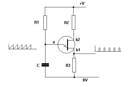
In the circuit, C charges via R1. When the voltage across C exceeds 0.6 volts, the b1/emitter junction goes low resistance and discharges C. The result is a sawtooth waveform across C.
There is also a pulse of current through R3 , giving a pulse of voltage across it. This circuit is called a relaxation oscillator. The voltage across C charges up slowly then suddenly relaxes.
The circuit is often used to trigger thyristor circuits.
