Testing Transistors Tutorial

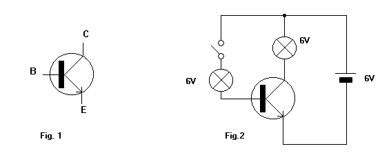
Figure 1. With the meter set to measure ohms, clip one meter lead to the base connection of the transistor. Touch the other lead first onto the collector lead and then onto the emitter lead. The readings should both be the same, either both high resistance or both low resistance.
Now reverse the leads and repeat the procedure. The results should be the opposite of those obtained before. If they were both high before they should now be both low. If they were both low before they should now both be high.
Now measure the resistance between emitter and collector. It should read high resistance in both directions. If you don't know the transistor connections consult a data book. If you cant find the data then measure between the three connections in both directions. You should now be able to identify the base connection and then decide if the transistor is OK.
Note that for this to work the internal battery of the meter must supply a voltage high enough to overcome the forward resistances of the transistors.
Many meter have a position marked with a diode symbol which must be selected when checking transistors or diodes.
Note that NPN transistors have low resistances where PNP have high, and vice versa.
Figure 2. shows a simple power transistor tester. With the switch open both lamps are off. With the switch closed both lamps are on. If different results are obtained the transistor is faulty. The transistor shown is an NPN. Reverse the battery for PNP transistors.
