Statics
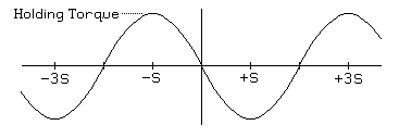
For a three-winding variable reluctance or permanent magnet motors with S radians per step, the period of the torque versus position curve will be 3S; for a 5-phase permanent magnet motor, the period will be 5S. For a two-winding permanent magnet or hybrid motor, the most common type, the period will be 4S, as illustrated in Figure 2.1:
Figure 2.1

Again, for an ideal 2 winding permanent magnet motor, this can be mathematically expressed as:
T = -h sin( ((π / 2) / S) θ )Where:
T -- torqueBut remember, subtle departures from the ideal sinusoid described here are very common.
h -- holding torque
S -- step angle, in radians
θ = shaft angle, in radians
The single-winding holding torque of a stepping motor is the peak value of the torque versus position curve when the maximum allowed current is flowing through one motor winding. If you attempt to apply a torque greater than this to the motor rotor while maintaining power to one winding, it will rotate freely.
It is sometimes useful to distinguish between the electrical shaft angle and the mechanical shaft angle. In the mechanical frame of reference, 2π radians is defined as one full revolution. In the electrical frame of reference, a revolution is defined as one period of the torque versus shaft angle curve. Throughout this tutorial, θ refers to the mechanical shaft angle, and ((π/2)/S)θ gives the electrical angle for a motor with 4 steps per cycle of the torque curve.
Assuming that the torque versus angular position curve is a good approximation of a sinusoid, as long as the torque remains below the holding torque of the motor, the rotor will remain within 1/4 period of the equilibrium position. For a two-winding permanent magnet or hybrid motor, this means the rotor will remain within one step of the equilibrium position.
With no power to any of the motor windings, the torque does not always fall to zero! In variable reluctance stepping motors, residual magnetization in the magnetic circuits of the motor may lead to a small residual torque, and in permanent magnet and hybrid stepping motors, the combination of pole geometry and the permanently magnetized rotor may lead to significant torque with no applied power.
The residual torque in a permanent magnet or hybrid stepping motor is frequently referred to as the cogging torque or detent torque of the motor because a naive observer will frequently guess that there is a detent mechanism of some kind inside the motor. The most common motor designs yield a detent torque that varies sinusoidally with rotor angle, with an equilibrium position at every step and an amplitude of roughly 10% of the rated holding torque of the motor, but a quick survey of motors from one manufacturer (Phytron) shows values as high as 23% for one very small motor to a low of 2.6% for one mid-sized motor.
