Living with Resonance
If a rigidly mounted stepping motor is rigidly coupled to a frictionless load and then stepped at a frequency near the resonant frequency, energy will be pumped into the resonant system, and the result of this is that the motor will literally lose control. There are three basic ways to deal with this problem:
Controlling resonance in the mechanism
Use of elastomeric motor mounts or elastomeric couplings between motor and load can drain energy out of the resonant system, preventing energy from accumulating to the extent that it allows the motor rotor to escape from control.
Or, viscous damping can be used. Here, the damping will not only draw energy out of the resonant modes of the system, but it will also subtract from the total torque available at higher speeds. Magnetic eddy current damping is equivalent to viscous damping for our purposes.
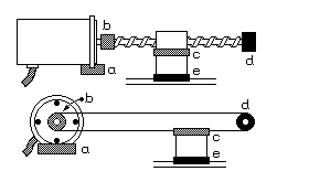
Figure 2.8 illustrates the use of elastomeric couplings and viscous damping in two typical stepping motor applications, one using a lead screw to drive a load, and the other using a tendon drive:
Figure 2.8

In Figure 2.8, elastomeric moter mounts are shown at a and elastomeric couplings between the motor and load are shown at b and c. The end bearing for the lead screw or tendon, at d, offers an opportunity for viscous damping, as do the ways on which the load slides, at e. Even the friction found in sealed ball bearings or Teflon on steel ways can provide enough damping to prevent resonance problems.
Controlling resonance in the low-level drive circuitry
A resonating motor rotor will induce an alternating current voltage in the motor windings. If some motor winding is not currently being driven, shorting this winding will impose a drag on the motor rotor that is exactly equivalent to using a magnetic eddy current damper.
If some motor winding is currently being driven, the AC voltage induced by the resonance will tend to modulate the current through the winding. Clamping the motor current with an external inductor will counteract the resonance. Schemes based on this idea are incorporated into some of the drive circuits illustrated in later sections of this tutorial.
Controlling resonance in the high-level control system
The high level control system can avoid driving the motor at known resonant frequencies, accelerating and decelerating through these frequencies and never attempting sustained rotation at these speeds.
Recall that the resonant frequency of a motor in half-stepped mode will vary by up to 20% from one half-step to the next. As a result, half-stepping pumps energy into the resonant system less efficiently than full stepping. Furthermore, when operating near these resonant frequencies, the motor control system may preferentially use only the two-winding half steps when operating near the single-winding resonant frequency, and only the single-winding half steps when operating near the two-winding resonant frequency. Figure 2.9 illustrates this:
Figure 2.9

The darkened curve in Figure 2.9 shows the operating torque achieved by a simple control scheme that delivers useful torque over a wide range of speeds despite the fact that the available torque drops to zero at each resonance in the system. This solution is particularly effective if the resonant frequencies are sharply defined and well separated. This will be the case in minimally damped systems operating well below the cutoff speed defined in the next section.
