Trigger Controls
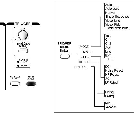
The trigger controls let you stabilize repeating waveforms and capture single-shot waveforms. Following Figure shows a typical front panel and on-screen menus for the trigger controls.

Trigger Controls
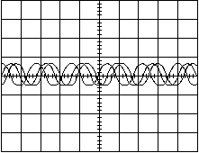
The trigger makes repeating waveforms appear static on the oscilloscope display. Imagine the jumble on the screen that would result if each sweep started at a different place on the signal (see Figure below).

Untriggered Display
Trigger Level and Slope
Your oscilloscope may have several different types of triggers, such as edge, video, pulse, or logic. Edge triggering is the basic and most common type and is the only type discussed in this book. Consult your oscilloscope instruction manual for details on other trigger types.
For edge triggering, the trigger level and slope controls provide the basic trigger point definition.
The trigger circuit acts as a comparator. You select the slope and voltage level of one side of the comparator. When the trigger signal matches your settings, the oscilloscope generates a trigger.
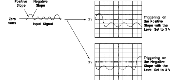
- The slope control determines whether the trigger point is on the rising or the falling edge of a signal. A rising edge is a positive slope and a falling edge is a negative slope.
- The level control determines where on the edge the trigger point occurs.
Following Figure shows you how the trigger slope and level settings determine how a waveform is displayed.

Positive and Negative Slope Triggering
Trigger Sources
The oscilloscope does not necessarily have to trigger on the signal being measured. Several sources can trigger the sweep:
- Any input channel
- An external source, other than the signal applied to an input channel
- The power source signal
- A signal internally generated by the oscilloscope
Most of the time you can leave the oscilloscope set to trigger on the channel displayed.
Note that the oscilloscope can use an alternate trigger source whether displayed or not. So you have to be careful not to unwittingly trigger on, for example, channel 1 while displaying channel 2.
Trigger Modes
The trigger mode determines whether or not the oscilloscope draws a waveform if it does not detect a trigger. Common trigger modes include normal and auto.
In normal mode the oscilloscope only sweeps if the input signal reaches the set trigger point; otherwise (on an analog oscilloscope) the screen is blank or (on a digital oscilloscope) frozen on the last acquired waveform. Normal mode can be disorienting since you may not see the signal at first if the level control is not adjusted correctly.
Auto mode causes the oscilloscope to sweep, even without a trigger. If no signal is present, a timer in the oscilloscope triggers the sweep. This ensures that the display will not disappear if the signal drops to small voltages. It is also the best mode to use if you are looking at many signals and do not want to bother setting the trigger each time.
In practice, you will probably use both modes: normal mode because it is more versatile and auto mode because it requires less adjustment.
Some oscilloscopes also include special modes for single sweeps, triggering on video signals, or automatically setting the trigger level.
Trigger Coupling
Just as you can select either AC or DC coupling for the vertical system, you can choose the kind of coupling for the trigger signal.
Besides AC and DC coupling, your oscilloscope may also have high frequency rejection, low frequency rejection, and noise rejection trigger coupling. These special settings are useful for eliminating noise from the trigger signal to prevent false triggering.
Trigger Holdoff
Sometimes getting an oscilloscope to trigger on the correct part of a signal requires great skill. Many oscilloscopes have special features to make this task easier.
Trigger holdoff is an adjustable period of time during which the oscilloscope cannot trigger. This feature is useful when you are triggering on complex waveform shapes, so that the oscilloscope only triggers on the first eligible trigger point. Following Figure shows how using trigger holdoff helps create a usable display.

Trigger Holdoff |