|

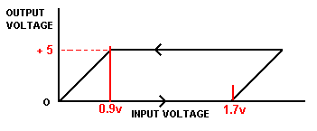
In the top diagram, the input voltage increases from zero, along the bottom horizontal line. The output voltage remains at zero on the vertical line.
However, when the input voltage reaches 1.7 volts, the output shoots up from zero to 5 volts.
Reducing the input voltage, as shown in the top horizontal line does not cause the output to drop to zero immediately. This only happens when the input voltage is reduced to 0.9 volts.
The input level at which the output increases to maximum, and the level at which it drops to zero are different. This is called
HYSTERESIS.

The black graph represents a noisy logic signal received from the moon. This is the input to the Schmitt Trigger.
The green graph is the output signal. The output remains at zero until the input exceeds 1.7 volts.
The output then shoots up to 5 volts and remains at 5 volts until the input drops to 0.9 volts.
The output then drops to zero.
An
almost
perfect
output
is
recovered
from a
very
noisy
input. |