|
author: Thomas Scarborough A crucial failing of proximity detectors is their unreliable and tricky nature. This is where they are used to detect humans, not to speak of smaller living beings. One common approach is to detect eddy currents in a living body, which are induced in the body through a.c. mains wiring. However, such circuits become altogether unusable in the case of mains failure, or in the absence of mains electricity, or even where adjacent mains circuits are switched in and out.

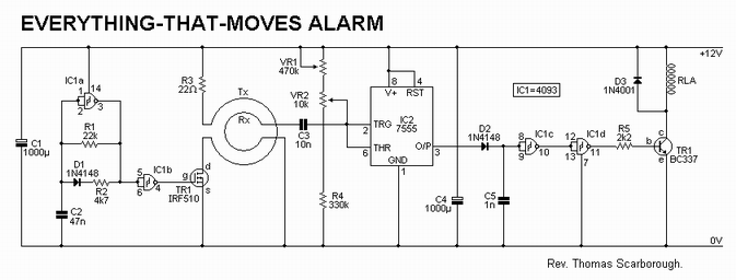
The circuit of Fig.1 takes the guesswork out of proximity detection by inducing eddy currents in a living being, whether animal or human. Five turns of enamelled copper wire (say 30 s.w.g.) are wound around the area within which detection is to take place (4m x 4m in tests), and an audio signal of about ¼ Watt is pulsed through this, the Tx, coil. A smaller Rx coil (say 100 turns of 30 s.w.g. enamelled copper wire wound on a 150mm dia. former) is used as a pick-up coil. The circuit is adjusted by means of tune and fine-tune controls VR1 and VR2, so that it is deactivated when one stands back from the Rx coil.
A simple clock generator (IC1a-IC1b) and power MOSFET (TR1) are used for the transmitter, and a 7555 timer (IC2) is wired as a sine-square convertor for the receiver. IC2's inputs are biased through VR1, VR2 and R4. IC2 in turn switches NAND gates IC1c and IC1d, to drive relay RLA. Capacitor C5 switches the relay for about two seconds, and its value may be increased or decreased to give different timing periods. D2 is critical to prevent back-e.m.f. from re-triggering the circuit. Supply decoupling capacitors C1 and C4 are also critical, and should be located close to IC1 and IC2 respectively.
When a living being - animal or human - comes within tens of centimetres of the Rx coil, the circuit is triggered. This coil may be placed in the threshold of a door, under a carpet, or around a hatch, at the base of a tree, and so on. A number of such coils may also be wired in series.
Coils may be wound with a larger or smaller diameter, with more or less turns, and the power of the transmitter may be varied, as well as the sensitivity of the receiver. Note that a.m. radio reception may be affected at close proximity to the Tx
coil. |