|

Notes:
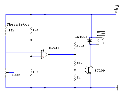
The thermistor used has a resistance of 15k at 25 degrees and 45k at 0 degrees celsius. A suitable bead type thermistor is found in the Maplin catalogue. The 100k pot allows this circuit to trigger over a wide range of temperatures. A slight amount of hysteresis
is provided by inclusion of the 270k resistor. This prevents relay chatter when
temperature is near the switching threshold of this circuit. |