|
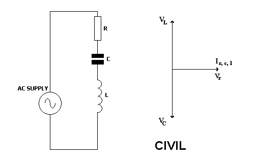
Since all three components are in series, the same current flows through them all.
This is shown by the horizontal phasor.
Since the resistor current and voltage are in phase, then resistor voltage is shown on the same phasor.
CIVIL is a remembering aid.
For a capacitor C, current I leads the voltage V by 90 degrees.
For an inductor L, voltage V leads the current I by 90 degrees.
If the voltage across the capacitor equals the voltage across the coil then, since they are 180 degrees out of phase, their effects will cancel out and we will be left with the effect of resistance only.
Z = R
The current and voltage in the circuit will be in phase.
I = V/R
All this happens when capacitive reactance equals inductive reactance.
Since capacitive reactance falls as frequency increases, and inductive reactance falls as frequency decreases, then there must be a frequency at which they are equal.
This is called the resonant frequency.

A series resonant circuit has a low impedance. |