|
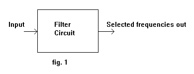
A filter circuit is like a sieve. It allows some things through and holds back others. In this case we are talking about AC frequencies. Some frequencies pass through the filter while others are rejected. 
The characteristics of a filter can be shown on a graph called a FREQUENCY RESPONSE CURVE.

VOLTAGE OUT is plotted against FREQUENCY.
Figure 2 shows a LOW PASS filter response curve giving output at low frequencies but none at higher frequencies.

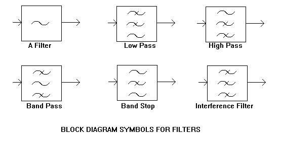
Figure 3 shows a selection of filter characteristics.
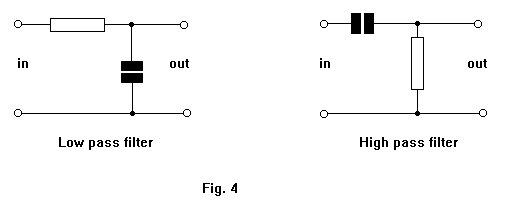
Simple filters can be made from capacitors and resistors.

Filters have many applications.
In audio frequency amplifiers, CROSSOVER filters to direct low frequencies to the
WOOFER and high frequencies to the TWEETER speakers.
In SCRATCH filters to remove unwanted high frequency noise.
In NOTCH filters to remove whistles due to two radio stations being too close together in frequency.
In Hum filters to remove low frequency noise due to the mains supply. |