|

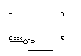
This flip-flop toggles (Q changes state) on the negative going edge of the clock pulse. T acts as an ENABLE / INHIBIT control. Q will only toggle on the negative edge of the clock pulse, when T is high. Below is shown a D type flip-flop connected as a toggle type. On each clock pulse positive going edge, Q will go to the state bar Q was before the clock pulse arrived. Remember that bar Q is the opposite level to Q. Therefore Q will toggle. 
|