|
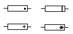
Diodes are polarised,
which means that they
must be inserted into
the PCB the correct way
round.
This is because an
electric current will
only flow through them
in one direction (like
air will only flow one
way through a tyre
valve). Diodes have two
connections, an anode
and a cathode. The
cathode is always
identified by a dot,
ring or some other mark.
 The pcb is often marked
with a + sign for the
cathode end.Diodes come in all
shapes and sizes.
They are often marked
with a type number.
Detailed characteristics
of a diode can be found
by looking up the type
number in a data book.
If you know how to
measure resistance with
a meter then test some
diodes.
A good one has
low resistance in one
direction and high in
the other.

There are specialised
types of diode available
such as the zener and
light emitting diode
(LED). |