|
Read the page on Cathode
Ray Tubes before reading
this.

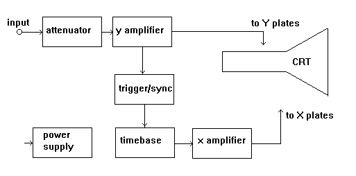
The signal to be
observed is applied to
the Y plates.
It is attenuated if it
is too large in
amplitude.
It is amplified if it is
too small in amplitude.
The time base generates
a saw tooth. (see page
on waveforms).
The saw tooth is
variable in frequency
and amplitude.
As the saw tooth voltage
rises, it causes the
spot to sweep from left
to right, across the
face of the CRT.
When the saw tooth
suddenly falls to zero,
the spot flies back to
the left of the screen
ready for another sweep.
This sweep and fly back
usually happens so
quickly that that the
display appears as a
straight line.
So we have the spot
being deflected
horizontally by the time
base, while the signal
is deflecting it
vertically, by means of
the Y plates.
The combination of
forces produces a
display which represents
the input signal.
To display one cycle,
the time base and signal
frequencies must be the
same. If the frequencies are
slightly different, the
display will drift
sideways. To avoid this , the
input signal is sampled
by the trigger circuit
and used to ensure that
the time base runs at
exactly the same
frequency as the input
signal. |