|
Read the pages on the
monochrome camera, and
light and colour.

Note that this page
describes the UK colour
system (PAL).
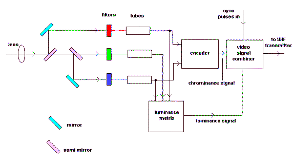
Light enters via the
lens on the left and is
split into three paths
by mirrors and
semi-transparent
mirrors.
The light in each path
passes through a colour
filter.
These filters are like
the transparent coloured
papers in which
chocolates are wrapped.
If you look through a
red one, everything
looks red.
This is because it lets
only red light through.
Blue or green objects
look black.
Colours which contain
some red, such as
purple, look dark red.
Red, blue and green
filters are used.
The coloured images are
focused on the faces of
the three colour tubes
which scan the images.
Each tube gives a signal
out, proportional to the
amount of colour.
Some of the red, green
and blue signals from
the camera tubes are
added in the luminance
matrix.
This means that the
separated colours are
recombined
electronically.
This gives a luminance
(brightness) signal.
The luminance signal is
labeled Ey, and is used
by black and white
receivers.
The colour signals are
known as Er, Eg, and Eb.
The red and blue signals
are converted into two
new signals called the
red and blue colour
difference signals.
They are (Er - Ey) and (Eb
- Ey).
These two signals are
modulated onto a "sub
carrier" at 4.43 MHz
which becomes the
chrominance (colour)
signal.
The luminance,
chrominance and sync
signals are combined and
are then used to
amplitude modulate a
carrier in the UHF band.
An associated sound
signal frequency
modulates a second
carrier, which is 6 MHz
apart from the vision
carrier. |