What Are SFRs?
The 8051
is a
flexible
microcontroller
with a
relatively
large
number
of modes
of
operations.
Your
program
may
inspect
and/or
change
the
operating
mode of
the 8051
by
manipulating
the
values
of the
8051's
Special
Function
Registers
(SFRs).
SFRs are
accessed
as if
they
were
normal
Internal
RAM. The
only
difference
is that
Internal
RAM is
from
address
00h
through
7Fh
whereas
SFR
registers
exist in
the
address
range of
80h
through
FFh.
Each SFR
has an
address
(80h
through
FFh) and
a name.
The
following
chart
provides
a
graphical
presentation
of the
8051's
SFRs,
their
names,
and
their
address.
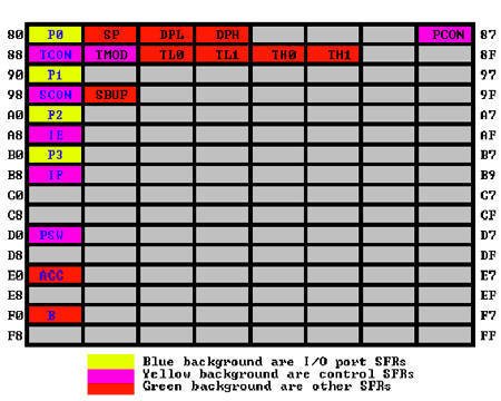
As you
can see,
although
the
address
range of
80h
through
FFh
offer
128
possible
addresses,
there
are only
21 SFRs
in a
standard
8051.
All
other
addresses
in the
SFR
range
(80h
through
FFh) are
considered
invalid.
Writing
to or
reading
from
these
registers
may
produce
undefined
values
or
behavior.
Programming
Tip:
It is
recommended
that you
not read
or write
to SFR
addresses
that
have not
been
assigned
to an
SFR.
Doing so
may
provoke
undefined
behavior
and may
cause
your
program
to be
incompatible
with
other
8051-derivatives
that use
the
given
SFR for
some
other
purpose.
SFR
Types
As
mentioned
in the
chart
itself,
the SFRs
that
have a
blue
background
are SFRs
related
to the
I/O
ports.
The 8051
has four
I/O
ports of
8 bits,
for a
total of
32 I/O
lines.
Whether
a given
I/O line
is high
or low
and the
value
read
from the
line are
controlled
by the
SFRs in
green.
The SFRs
with
yellow
backgrouns
are SFRs
which in
some way
control
the
operation
or the
configuration
of some
aspect
of the
8051.
For
example,
TCON
controls
the
timers,
SCON
controls
the
serial
port.
The
remaining
SFRs,
with
green
backgrounds,
are
"other
SFRs."
These
SFRs can
be
thought
of as
auxillary
SFRs in
the
sense
that
they
don't
directly
configure
the 8051
but
obviously
the 8051
cannot
operate
without
them.
For
example,
once the
serial
port has
been
configured
using
SCON,
the
program
may read
or write
to the
serial
port
using
the
SBUF
register.
Programming
Tip:
The SFRs
whose
names
appear
in red
in the
chart
above
are SFRs
that may
be
accessed
via bit
operations
(i.e.,
using
the
SETB
and
CLR
instructions).
The
other
SFRs
cannot
be
accessed
using
bit
operations.
As you
can see,
all SFRs
that
whose
addresses
are
divisible
by 8 can
be
accessed
with bit
operations.
SFR
Descriptions
This
section
will
endeavor
to
quickly
overview
each of
the
standard
SFRs
found in
the
above
SFR
chart
map. It
is not
the
intention
of this
section
to fully
explain
the
functionality
of each
SFR--this
information
will be
covered
in
separate
chapters
of the
tutorial.
This
section
is to
just
give you
a
general
idea of
what
each SFR
does.
P0 (Port 0, Address 80h, Bit-Addressable):
This is
input/output
port 0.
Each bit
of this
SFR
corresponds
to one
of the
pins on
the
microcontroller.
For
example,
bit 0 of
port 0
is pin
P0.0,
bit 7 is
pin
P0.7.
Writing
a value
of 1 to
a bit of
this SFR
will
send a
high
level on
the
corresponding
I/O pin
whereas
a value
of 0
will
bring it
to a low
level.
Programming
Tip:
While
the 8051
has four
I/O port
(P0, P1,
P2, and
P3), if
your
hardware
uses
external
RAM or
external
code
memory
(i.e.,
your
program
is
stored
in an
external
ROM or
EPROM
chip or
if you
are
using
external
RAM
chips)
you may
not use
P0 or
P2. This
is
because
the 8051
uses
ports P0
and P2
to
address
the
external
memory.
Thus if
you are
using
external
RAM or
code
memory
you may
only use
ports P1
and P3
for your
own use.
SP
(Stack
Pointer,
Address
81h):
This is
the
stack
pointer
of the
microcontroller.
This SFR
indicates
where
the next
value to
be taken
from the
stack
will be
read
from in
Internal
RAM. If
you push
a value
onto the
stack,
the
value
will be
written
to the
address
of SP +
1. That
is to
say, if
SP holds
the
value
07h, a
PUSH
instruction
will
push the
value
onto the
stack at
address
08h.
This SFR
is
modified
by all
instructions
which
modify
the
stack,
such as
PUSH,
POP,
LCALL,
RET,
RETI,
and
whenever
interrupts
are
provoked
by the
microcontroller.
Programming Tip:
The SP
SFR, on
startup,
is
initialized
to 07h.
This
means
the
stack
will
start at
08h and
start
expanding
upward
in
internal
RAM.
Since
alternate
register
banks 1,
2, and 3
as well
as the
user bit
variables
occupy
internal
RAM from
addresses
08h
through
2Fh, it
is
necessary
to
initialize
SP in
your
program
to some
other
value if
you will
be using
the
alternate
register
banks
and/or
bit
memory.
It's not
a bad
idea to
initialize
SP to
2Fh as
the
first
instruction
of every
one of
your
programs
unless
you are
100%
sure you
will not
be using
the
register
banks
and bit
variables.
DPL/DPH
(Data
Pointer
Low/High,
Addresses
82h/83h):
The SFRs
DPL and
DPH work
together
to
represent
a 16-bit
value
called
the
Data
Pointer.
The data
pointer
is used
in
operations
regarding
external
RAM and
some
instructions
involving
code
memory.
Since it
is an
unsigned
two-byte
integer
value,
it can
represent
values
from
0000h to
FFFFh (0
through
65,535
decimal).
Programming Tip:
DPTR is
really
DPH and
DPL
taken
together
as a
16-bit
value.
In
reality,
you
almost
always
have to
deal
with
DPTR one
byte at
a time.
For
example,
to push
DPTR
onto the
stack
you must
first
push DPL
and then
DPH. You
can't
simply
plush
DPTR
onto the
stack.
Additionally,
there is
an
instruction
to
"increment
DPTR."
When you
execute
this
instruction,
the two
bytes
are
operated
upon as
a 16-bit
value.
However,
there is
no
instruction
that
decrements
DPTR. If
you wish
to
decrement
the
value of
DPTR,
you must
write
your own
code to
do so.
PCON
(Power
Control,
Addresses
87h):
The
Power
Control
SFR is
used to
control
the
8051's
power
control
modes.
Certain
operation
modes of
the 8051
allow
the 8051
to go
into a
type of
"sleep"
mode
which
requires
much
less
power.
These
modes of
operation
are
controlled
through
PCON.
Additionally,
one of
the bits
in PCON
is used
to
double
the
effective
baud
rate of
the
8051's
serial
port.
TCON
(Timer
Control,
Addresses
88h,
Bit-Addressable):
The
Timer
Control
SFR is
used to
configure
and
modify
the way
in which
the
8051's
two
timers
operate.
This SFR
controls
whether
each of
the two
timers
is
running
or
stopped
and
contains
a flag
to
indicate
that
each
timer
has
overflowed.
Additionally,
some
non-timer
related
bits are
located
in the
TCON
SFR.
These
bits are
used to
configure
the way
in which
the
external
interrupts
are
activated
and also
contain
the
external
interrupt
flags
which
are set
when an
external
interrupt
has
occured.
TMOD
(Timer
Mode,
Addresses
89h):
The
Timer
Mode SFR
is used
to
configure
the mode
of
operation
of each
of the
two
timers.
Using
this SFR
your
program
may
configure
each
timer to
be a
16-bit
timer,
an 8-bit
autoreload
timer, a
13-bit
timer,
or two
separate
timers.
Additionally,
you may
configure
the
timers
to only
count
when an
external
pin is
activated
or to
count
"events"
that are
indicated
on an
external
pin.
TL0/TH0
(Timer 0
Low/High,
Addresses
8Ah/8Ch):
These
two
SFRs,
taken
together,
represent
timer 0.
Their
exact
behavior
depends
on how
the
timer is
configured
in the
TMOD
SFR;
however,
these
timers
always
count
up. What
is
configurable
is how
and when
they
increment
in
value.
TL1/TH1
(Timer 1
Low/High,
Addresses
8Bh/8Dh):
These
two
SFRs,
taken
together,
represent
timer 1.
Their
exact
behavior
depends
on how
the
timer is
configured
in the
TMOD
SFR;
however,
these
timers
always
count
up. What
is
configurable
is how
and when
they
increment
in
value.
P1 (Port
1,
Address
90h,
Bit-Addressable):
This is
input/output
port 1.
Each bit
of this
SFR
corresponds
to one
of the
pins on
the
microcontroller.
For
example,
bit 0 of
port 1
is pin
P1.0,
bit 7 is
pin
P1.7.
Writing
a value
of 1 to
a bit of
this SFR
will
send a
high
level on
the
corresponding
I/O pin
whereas
a value
of 0
will
bring it
to a low
level.
SCON
(Serial
Control,
Addresses
98h,
Bit-Addressable):
The
Serial
Control
SFR is
used to
configure
the
behavior
of the
8051's
on-board
serial
port.
This SFR
controls
the baud
rate of
the
serial
port,
whether
the
serial
port is
activated
to
receive
data,
and also
contains
flags
that are
set when
a byte
is
successfully
sent or
received.
Programming Tip:
To use
the
8051's
on-board
serial
port, it
is
generally
necessary
to
initialize
the
following
SFRs:
SCON,
TCON,
and
TMOD.
This is
because
SCON
controls
the
serial
port.
However,
in most
cases
the
program
will
wish to
use one
of the
timers
to
establish
the
serial
port's
baud
rate. In
this
case, it
is
necessary
to
configure
timer 1
by
initializing
TCON and
TMOD.
SBUF
(Serial
Control,
Addresses
99h):
The
Serial
Buffer
SFR is
used to
send and
receive
data via
the
on-board
serial
port.
Any
value
written
to SBUF
will be
sent out
the
serial
port's
TXD pin.
Likewise,
any
value
which
the 8051
receives
via the
serial
port's
RXD pin
will be
delivered
to the
user
program
via
SBUF. In
other
words,
SBUF
serves
as the
output
port
when
written
to and
as an
input
port
when
read
from.
P2 (Port
2,
Address
A0h,
Bit-Addressable):
This is
input/output
port 2.
Each bit
of this
SFR
corresponds
to one
of the
pins on
the
microcontroller.
For
example,
bit 0 of
port 2
is pin
P2.0,
bit 7 is
pin
P2.7.
Writing
a value
of 1 to
a bit of
this SFR
will
send a
high
level on
the
corresponding
I/O pin
whereas
a value
of 0
will
bring it
to a low
level.
Programming Tip:
While
the 8051
has four
I/O port
(P0, P1,
P2, and
P3), if
your
hardware
uses
external
RAM or
external
code
memory
(i.e.,
your
program
is
stored
in an
external
ROM or
EPROM
chip or
if you
are
using
external
RAM
chips)
you may
not use
P0 or
P2. This
is
because
the 8051
uses
ports P0
and P2
to
address
the
external
memory.
Thus if
you are
using
external
RAM or
code
memory
you may
only use
ports P1
and P3
for your
own use.
IE
(Interrupt
Enable,
Addresses
A8h):
The
Interrupt
Enable
SFR is
used to
enable
and
disable
specific
interrupts.
The low
7 bits
of the
SFR are
used to
enable/disable
the
specific
interrupts,
where as
the
highest
bit is
used to
enable
or
disable
ALL
interrupts.
Thus, if
the high
bit of
IE is 0
all
interrupts
are
disabled
regardless
of
whether
an
individual
interrupt
is
enabled
by
setting
a lower
bit.
P3 (Port
3,
Address
B0h,
Bit-Addressable):
This is
input/output
port 3.
Each bit
of this
SFR
corresponds
to one
of the
pins on
the
microcontroller.
For
example,
bit 0 of
port 3
is pin
P3.0,
bit 7 is
pin
P3.7.
Writing
a value
of 1 to
a bit of
this SFR
will
send a
high
level on
the
corresponding
I/O pin
whereas
a value
of 0
will
bring it
to a low
level.
IP
(Interrupt
Priority,
Addresses
B8h,
Bit-Addressable):
The
Interrupt
Priority
SFR is
used to
specify
the
relative
priority
of each
interrupt.
On the
8051, an
interrupt
may
either
be of
low (0)
priority
or high
(1)
priority.
An
interrupt
may only
interrupt
interrupts
of lower
priority.
For
example,
if we
configure
the 8051
so that
all
interrupts
are of
low
priority
except
the
serial
interrupt,
the
serial
interrupt
will
always
be able
to
interrupt
the
system,
even if
another
interrupt
is
currently
executing.
However,
if a
serial
interrupt
is
executing
no other
interrupt
will be
able to
interrupt
the
serial
interrupt
routine
since
the
serial
interrupt
routine
has the
highest
priority.
PSW
(Program
Status
Word,
Addresses
D0h,
Bit-Addressable):
The
Program
Status
Word is
used to
store a
number
of
important
bits
that are
set and
cleared
by 8051
instructions.
The PSW
SFR
contains
the
carry
flag,
the
auxiliary
carry
flag,
the
overflow
flag,
and the
parity
flag.
Additionally,
the PSW
register
contains
the
register
bank
select
flags
which
are used
to
select
which of
the "R"
register
banks
are
currently
selected.
Programming Tip:
If you
write an
interrupt
handler
routine,
it is a
very
good
idea to
always
save the
PSW SFR
on the
stack
and
restore
it when
your
interrupt
is
complete.
Many
8051
instructions
modify
the bits
of PSW.
If your
interrupt
routine
does not
guarantee
that PSW
is the
same
upon
exit as
it was
upon
entry,
your
program
is bound
to
behave
rather
erradically
and
unpredictably--and
it will
be
tricky
to debug
since
the
behavior
will
tend not
to make
any
sense.
ACC
(Accumulator,
Addresses
E0h,
Bit-Addressable):
The
Accumulator
is one
of the
most-used
SFRs on
the 8051
since it
is
involved
in so
many
instructions.
The
Accumulator
resides
as an
SFR at
E0h,
which
means
the
instruction
MOV
A,#20h
is
really
the same
as
MOV
E0h,#20h.
However,
it is a
good
idea to
use the
first
method
since it
only
requires
two
bytes
whereas
the
second
option
requires
three
bytes.
B (B
Register,
Addresses
F0h,
Bit-Addressable):
The "B"
register
is used
in two
instructions:
the
multiply
and
divide
operations.
The B
register
is also
commonly
used by
programmers
as an
auxiliary
register
to
temporarily
store
values.
Other
SFRs
The
chart
above is
a
summary
of all
the SFRs
that
exist in
a
standard
8051.
All
derivative
microcontrollers
of the
8051
must
support
these
basic
SFRs in
order to
maintain
compatability
with the
underlying
MSCS51
standard.
A common
practice
when
semiconductor
firms
wish to
develop
a new
8051
derivative
is to
add
additional
SFRs to
support
new
functions
that
exist in
the new
chip.
For
example,
the
Dallas
Semiconductor
DS80C320
is
upwards
compatible
with the
8051.
This
means
that any
program
that
runs on
a
standard
8051
should
run
without
modification
on the
DS80C320.
This
means
that all
the SFRs
defined
above
also
apply to
the
Dallas
component.
However,
since
the
DS80C320
provides
many new
features
that the
standard
8051
does
not,
there
must be
some way
to
control
and
configure
these
new
features.
This is
accomplished
by
adding
additional
SFRs to
those
listed
here.
For
example,
since
the
DS80C320
supports
two
serial
ports
(as
opposed
to just
one on
the
8051),
the SFRs
SBUF2
and
SCON2
have
been
added.
In
addition
to all
the SFRs
listed
above,
the
DS80C320
also
recognizes
these
two new
SFRs as
valid
and uses
their
values
to
determine
the mode
of
operation
of the
secondary
serial
port.
Obviously,
these
new SFRs
have
been
assigned
to SFR
addresses
that
were
unused
in the
original
8051. In
this
manner,
new 8051
derivative
chips
may be
developed
which
will run
existing
8051
programs.
Programming
Tip:
If you
write a
program
that
utilizes
new SFRs
that are
specific
to a
given
derivative
chip and
not
included
in the
above
SFR
list,
your
program
will not
run
properly
on a
standard
8051
where
that SFR
does not
exist.
Thus,
only use
non-standard
SFRs if
you are
sure
that
your
program
wil only
have to
run on
that
specific
microcontroller.
Likewise,
if you
write
code
that
uses
non-standard
SFRs and
subsequently
share it
with a
third-party,
be sure
to let
that
party
know
that
your
code is
using
non-standard
SFRs to
save
them the
headache
of
realizing
that due
to
strange
behavior
at
run-time.
<<< Click
here to
come
back on
(Special
Function
Registers)