LED Traffic Lights Project to Save Energy
14 STAGE RIPPLE-CARRY BINARY COUNTER / DIVIDER AND OSCILLATOR
This attractive chip can be easily used for the realization of a variable frequency oscillator, used in the functions of calibrator frequency, low frequency generator, precision clock logic circuits, multivibrators speed fast, medium, long, long, timers.
This is an asynchronous counter. For completeness, we say that the counters are distinguished from asynchronous to synchronous switching of the fact that the later stages does not occur simultaneously with the transition of the clock signal, the switching, in fact, propagate, starting from the front of the clock, with a delay on gradually increasing from one stage to another, each adding to the signal with a delay of time to evaluate the tens of nanoseconds or more. This is not acceptable in many practical applications, such as in multi-stage counter sync signals, while in the case of timers that usually does not cause any inconvenience. Moreover, synchronous counters can not work with these very high frequencies with which the asynchronous work, the same component technology used, since the half-cycle can not be shorter than the sum of the different delay times of the various stages.
Asynchronous counters also have internal circuitry simpler, because the outputs of individual stages are not conditioned by the clock signal to implement the synchronous switching.
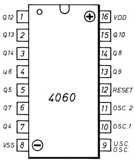
The chip B 4060 is made of metal gate Complementary MOS technology, known as CMOSB, able to work with high voltages, up to 18 VDC, providing an excellent noise immunity and be suitable for industrial applications, highly reliable. The pin in question is interpreted in the integrated design of Figure 1.

Figure 1 - Symbol of the legs of the integrated electrical and Map B. 4060
The terminals are marked with the letters Q outputs of flip-flop inside, which divides the frequency. The pin Q10, for example, is the output of the flip-flop No. 10. (The value of division and '2 ^ 10 = 1024).
The pin 12 is RESET, which is normally connected to VSS, ie with the negative supply line or mass, and as 'the active and' higher value.
Terminals and marked with the initials OSC.1 OSC.2 represent the inputs that are rocking the house contained a special stage of integration.
The terminal 9, marked with USC. OSC., Proposes the oscillator frequency amplifier stage after a separator.
The circuit, shown in figure 2, interpretation of the integrated function diagram 4060 B.

Fig 2 - Block diagram of the integrated 4060 B.
In it, the numbering refers to that same pin numbering scheme in Figure 1. On the right of the rectangle are mentioned outputs available and the underlying health of the division.

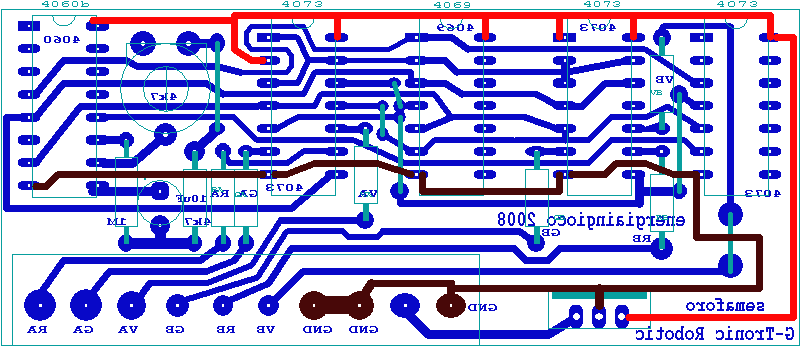
Click on the circuit diagram for clearer view
Download file FidoCAD single specimen of the PCB
Donwnload files FidoCAD 1 1 traffic light digital clock and a power supply (100x160mm)


