24 Hour Timer Circuit Tutorial
Description:
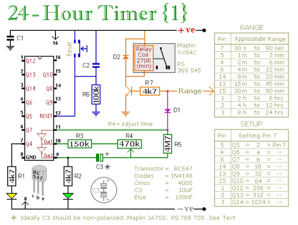
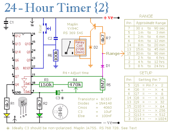
These two circuits are multi-range timers offering periods of up to 24 hours and beyond. Both are essentially the same. The main difference is that when the time runs out, Version 1 energizes the relay and Version 2 de-energizes it. The first uses less power while the timer is running; and the second uses less power after the timer stops. Pick the one that best suits your application.
Notes:
The Cmos 4060 is a 14 bit binary counter with a built in oscillator. The oscillator consists of the two inverters connected to Pins 9, 10 & 11; and its frequency is set by R3, R4 & C3. The green Led flashes while the oscillator is running: and the IC counts the number of oscillations. Although it's a 14 bit counter, not all of the bits are accessible. Those that can be reached are shown on the drawing.
By adjusting the frequency of the oscillator you can set the length of time it takes for any given output to go high. This output then switches the transistor; which in turn operates the relay. At the same time, D1 stops the count by disabling the oscillator. Ideally C3 should be non-polarized; but a regular electrolytic will work, provided it doesn't leak too badly in the reverse direction. Alternatively, you can simulate a non-polarized 10uF capacitor by connecting two 22uF capacitors back to back (as shown).
Using "Trial and Error" to set a long time period would be very tedious. A better solution is to use the Setup tables provided; and calculate the time required for Pin 7 to go high. The Setup tables on both schematics are interchangeable. They're just two different ways of expressing the same equation.
For example, if you want a period of 9 Hours, the Range table shows that you can use the output at Pin 2. You need Pin 2 to go high after 9 x 60 x 60 = 32 400 seconds. The Setup table tells you to divide this by 512; giving about 63 seconds. Adjust R4 so that the Yellow LED lights 63 seconds after power is applied. This will give an output at Pin 2 after about 9 Hours. A suitable Veroboard layout for each version is shown below: