Electronic Circuits and Tutorials
Facebook
The Diode - Electronic Tutorials
Voltage Doubler Tutorial
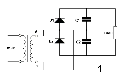
It's best to read the page on the half-wave rectifier, first.
Point A is doing the opposite of point B.
As A increases in a positive direction, B increases negatively, and vice-versa.
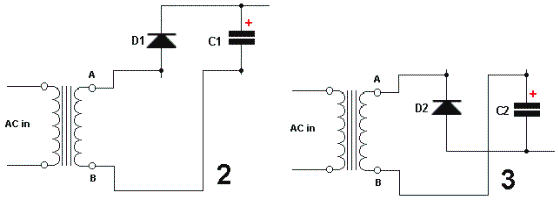
When A is positive, D1 is forward biased and charges C1 to the peak voltage, as in diagram 2.
D 2 is reverse biased and does not conduct.
When A goes negative, D1 is reverse biased and does not conduct.
D2 is forward biased and charges C2 to the peak voltage, as in diagram 3.
We now have two capacitors in series, each charged to the peak voltage.
The voltage across the load is. therefore, twice the peak voltage.
The voltage has been doubled.