Bipolar Chopper
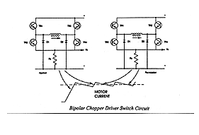
Bipolar chopper drivers are by far the most widely used drivers for industrial applications. Although they are typically more expensive to design, they offer high performance and high efficiency. Bipolar chopper drivers use an extra set of switching transistors to eliminate the need for two power sources. Additionally, these drivers use a four transistor bridge with recirculating diodes and a sense resistor that maintains a feedback voltage proportional to the motor current. Motor windings, using a bipolar chopper driver, are energized to the full supply level by turning on one set (top and bottom) of the switching transistors.
The sense resistor monitors the linear rise in current until the required level is reached. At this point the top switch opens and the current in the motor coil is maintained via the bottom switch and the diode. Current "decay" (lose over time) occurs until a preset position is reached and the process starts over. This "chopping" effect of the supply is what maintains the correct current voltage to the motor at all times.

