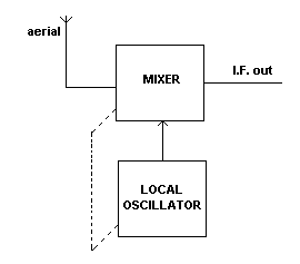
It is best if you read the page on THE MIXER first. There are many thousands of radio stations in the world, transmitting on thousands of different frequencies. Radio waves from these stations hit your radio aerial and induce voltages in it.
It is the TUNING circuit in your radio which selects the one station that you are interested in, and rejects all the others. The tuning circuit is usually a coil and a variable capacitor. The value of the capacitor is adjusted so that the tuning circuit is at the frequency of the wanted station.
It is the job of the frequency changer to change the frequency of the selected station to a new, lower, fixed frequency. This new frequency is called the
INTERMEDIATE frequency (I.F.). No matter what the frequency of the selected station is, it is changed to the I.F. This is about 455 kHz for AM radios and 10.7 MHz for FM radios.
This frequency changing is done by mixing the radio frequency with the frequency generated by a local oscillator. The local oscillator frequency is also controlled by a coil and variable capacitor.
The output from the mixer is the difference in frequency between the two input frequencies.
For example, if the radio station is on 110.7 MHz and the local oscillator is at 100 MHz then the I.F. is 110.7-100 = 10.7 MHZ.
Since the tuning circuit has to be changed in frequency every time you change stations, then the local oscillator frequency has to be changed to keep the difference at 10.7 MHz. Therefore the two variable capacitors are
GANGED together.
This means that they are both mounted on a common shaft, and when one is adjusted the other is similarly changed. This is represented by the broken line in the diagram. |