|
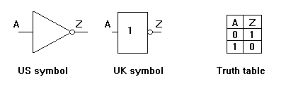
The NOT gate has a single input and one output.
The little bubble on the output indicates that the output goes LOW when the input goes HIGH.
We can say that the output goes LOW when the input is ACTIVATED.
The opposite happens when the input is LOW. The output goes HIGH.
The TRUTH TABLE shows that the output is the opposite of the input.
The NOT gate is also called an INVERTER. It inverts the input.
_
The Boolean expression is A = Z
Which is read as, NOT A EQUALS Z
or IF A IS LOW THEN Z IS HIGH
or BAR A = Z |