|

Logic gates usually come packaged as integrated circuits which have type numbers such as 7400 or 4001.
They belong to semiconductor families such as TTL (transistor, transistor logic) or CMOS (complementary metal oxide semiconductor). The names describe their internal construction.
They are DIGITAL devices not ANALOGUE.
A thermometer is an analogue device because it can record an infinite number of values such 100 degrees, 0.1 degrees or 34.354 degrees etc.
Other analogue devices are a car speedo and a Hi Fi amplifier (which can handle lots of different frequencies and
loudness.)
A digital device or system uses only two values. These can be expressed in several ways.
high or low
true or false
5 volts or zero volts
on or off
1 or 0
etc.
A light switch and a rat trap are digital devices.
Most gates usually have two or more inputs and one output.

The state of the output (high or low) depends upon the combination of the input states.
In the case of the gate shown, the output will only be high if both inputs are high. If either one input or both inputs are low then the output will be low.
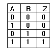
These characteristics can be shown using a TRUTH TABLE. In the following example 1 indicates a high and 0 indicates a low.
Note that Z is only a 1 when A AND B are both at 1.
There is a form of mathematics associated with logic gates called BOOLEAN ALGEBRA.
It was invented a few hundred years ago by Mr Boole, before the days of electronics. He used it to solve problems in logic.
For example
Some cats are black AND black items cannot be seen against a black wall.
Therefore it is TRUE that some cats cannot be seen against a black wall.
Here is a Boolean expression for the gate shown. A . B = Z.
Read this as IF A AND B ARE HIGH THEN Z IS HIGH. (The . is read as AND).
The most frequently used gates are AND, OR, NAND, NOR, NOT and EXOR.
An integrated circuit containing 4 AND gates each with 2 inputs is called a QUAD 2 INPUT AND ic. An ic with 6 NOT gates is called a HEX INVERTER ic. |