|
Read the page on multivibrators first. The output of the bistable
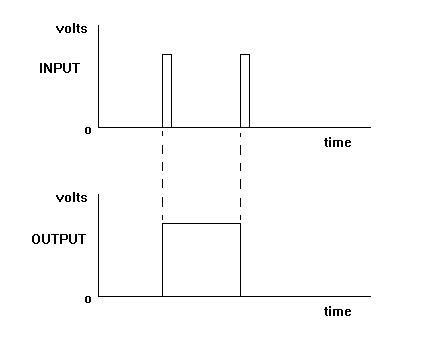
toggles (changes state) when its input receives a pulse.
This means that after two pulses the output has returned to its original state.
If it was originally low, it has gone high after the first pulse and then returned low after the second.

Looking at the first diagram, the two input pulses have provided a single, wider pulse at the output.
If we put eight pulses in then we get four out. The bistable divides by two.
If we put a 16 kHz signal in, we get an 8 kHz signal out. The bistable acts as a frequency divider.
If we feed the 8 kHz into another bistable the resulting frequency is 4 kHz. We can divide a high frequency signal down to a lower one.
 |